Lately I’ve been thinking about Stephan Berger’s recent blog post on hiding Linux processes with bind mounts. Bottom line here is that if you have an evil process you want to hide, use a bind mount to mount a different directory on top of the /proc/PID directory for the evil process.
In the original article, Stephan uses a nearly empty directory to overlay the original /proc/PID directory for the process he is hiding. I started thinking about how I could write a tool that would populate a more realistic looking spoofed directory. But after doing some prototypes and running into annoying complexities I realized there is a much easier approach.
Why try and make my own spoofed directory when I can simply use an existing /proc/PID directory from some other process? If you look at typical Linux ps output, there are lots of process entries that would hide our evil process quite well:
These process entries with low PIDs and process names in square brackets (“[somename]“) are spontaneous processes. They aren’t running executables in the traditional sense– you won’t find a binary in your operating system called kthreadd for example. Instead, these are essentially kernel code dressed up to look like a process so administrators can monitor various subsystems using familiar tools like ps.
From our perspective, however, they’re a bunch of processes that administrators generally ignore and which have names that vary only slightly from one another. They’re perfect for hiding our evil processes:
Our evil process is now completely hidden. If somebody were to look closely at the ps output, they would discover there are now two entries for PID 78:
My guess is that nobody is going to notice this unless they are specifically looking for this technique. And if they are aware of this technique, there’s a much simpler way of detecting it which Stephan notes in his original article:
Just to be thorough, I’m dumping the content of all /proc/*/mount entries (/proc/mounts is a link to /proc/self/mounts) and looking for ones where the mount point is a /proc/PIDdirectory or one of its subdirectories. The “sort -ur” at the end gives us one instance of each unique mount point.
But why the “-r” option? I want to use my output to programmatically unmount the bind mounted directories. I was worried about somebody doing a bind mount on top of a bind mount:
While I think this scenario is extremely unlikely, using “sort -ur” means that the mount points are returned in the proper order to be unmounted. And once the bind mounts are umounted, we can see the evil process again.
Note that we do get an error here. /proc/78 is mounted on top of /proc/4867. So when we unmount /proc/78/fd we are also taking care of the spoofed path /proc/4867/fd. When our while loop gets to the entry for /proc/4867/fd, the umount command errors out.
Possible weird corner cases aside, let’s try and provide our analyst with some additional information:
root@LAB:~# function procbindmounts {
  cat /proc/*/mounts | awk '$2 ~ /^\/proc\/[0-9]*($|\/)/ { print $2 }' | sort -ur |
    while read dir; do
        echo ===== POSSIBLE PROCESS HIDING $dir
        echo -ne Overlay:\\t
        cut -d' ' -f1-7 $dir/stat
        umount $dir
        echo -ne Hidden:\\t\\t
        cut -d' ' -f1-7 $dir/stat
    done
}
root@LAB:~# mount -B /proc/78 /proc/4867
root@LAB:~# procbindmounts
===== POSSIBLE PROCESS HIDING /proc/4867
Overlay:        78 (irq/29-pciehp) S 2 0 0 0
Hidden:         4867 (myevilprocess) S 1 4867 4759 34816
Thanks Stephan for getting my creative juices flowing. This is a fun technique for all you red teamers out there, and a good trick for all you blue team analysts.
In my last blog post, I covered Systemd timers and some of the forensic artifacts associated with them. I’m also a fan of Thiago Canozzo Lahr’s UAC tool for collecting artifacts during incident response. So I wanted to add the Systemd timer artifacts covered in my blog post to UAC. And it occurred to me that others might be interested in seeing how to modify UAC to add new artifacts for their own purposes.
UAC is a module-driven tool for collecting artifacts from Unix-like systems (including Macs). The user specifies a profile file containing the list of artifacts they want to collect and an output directory where that collection should occur. Individual artifacts may be added to or excluded from the list of artifacts in the profile file using individual command line arguments.
A typical UAC command might look like:
./uac -p ir_triage -a memory_dump/avml.yaml /root
Here we are selecting the standard ir_triage profile included with UAC (“-p ir_triage“) and adding a memory dump (“-a memory_dump/avml.yaml“) to the list of artifacts to be collected. Output will be collected in the /root directory.
UAC’s configuration files are simple YAML configuration files and can be easily customized and modified to fit your needs. Adding new artifacts usually means adding a few lines to existing configuration files, or rarely creating a new configuration module from scratch. I’m going to walk through a few examples, including showing you how I added the Systemd timer artifacts to UAC.
Before we get started, let’s go ahead and check out the latest version from Thiago’s Github:
The profiles directory contains the YAML formated profile files, including the ir_triage.yaml profile I referenced in my sample UAC command above:
$ ls profiles/
full.yaml  ir_triage.yaml  offline.yaml
The artifacts directory is an entire hierarchy of dozens of YAML files describing how to collect artifacts:
$ ls artifacts/
bodyfile  chkrootkit  files  hash_executables  live_response  memory_dump
$ ls artifacts/memory_dump/
avml.yaml  process_memory_sections_strings.yaml  process_memory_strings.yaml
Modifying Profiles
While the default profiles that come with UAC are excellent starting points, you will often find yourself needing to tweak the list of artifacts you wish to collect. This can be done with the “-a” command line argument as noted above. But if you find yourself collecting the same custom list of artifacts over and over, it becomes easier to create your own profile file with your specific list of desired artifacts.
For example, let’s suppose were were satisfied with the basic list of artifacts in the ir_triage profile, but wanted to make sure we always tried to collect a memory image. Rather than adding “-a memory_dump/avml.yaml” to every UAC command, we could create a modified version of the ir_triage profile that simply includes this artifact.
First make a copy of the ir_triage profile under a new name:
You can see where we added the “memory_dump/avml.yaml” artifact right at the top of the list of artifacts to collect. It is also extremely important to modify the “name:” line at the top of the file so that this name matches the name of the YAML file for the profile (without the “.yaml” extension). UAC will exit with an error if the “name:” line doesn’t match the base name of the profile file you are trying to use.
Now that we have our new profile file, we can invoke it as “./uac -p ir_triage_memory /root“.
Adding Artifacts
To add specific artifacts, you will need to get into the YAML files under the “artifacts” directory. In my previous blog posting, I suggested collecting the output of “systemctl list-timers --all” and “systemctl status *.timers“. You’ll often be surprised to find that UAC is already collecting the artifact you are looking for:
version: 1.0
artifacts:
  -
    description: Display all systemd system units.
    supported_os: [linux]
    collector: command
    command: systemctl list-units
    output_file: systemctl_list-units.txt
  -
    description: Display timer units currently in memory, ordered by the time they elapse next.
    supported_os: [linux]
    collector: command
    command: systemctl list-timers --all
    output_file: systemctl_list-timers_--all.txt
  -
    description: Display unit files installed on the system, in combination with their enablement state (as reported by is-enabled).
    supported_os: [linux]
    collector: command
    command: systemctl list-unit-files
    output_file: systemctl_list-unit-files.txt
It looks like “systemctl list-timers --all” is already being collected. Following the pattern of the other entries, it’s easy to add in the configuration to collect “systemctl status *.timers“:
version: 1.1
artifacts:
  -
    description: Display all systemd system units.
    supported_os: [linux]
    collector: command
    command: systemctl list-units
    output_file: systemctl_list-units.txt
  -
    description: Display timer units currently in memory, ordered by the time they elapse next.
    supported_os: [linux]
    collector: command
    command: systemctl list-timers --all
    output_file: systemctl_list-timers_--all.txt
  -
    description: Get status from all timers, including logs
    supported_os: [linux]
    collector: command
    command: systemctl status *.timer
    output_file: systemctl_status_timer.txt
  -
    description: Display unit files installed on the system, in combination with their enablement state (as reported by is-enabled).
    supported_os: [linux]
    collector: command
    command: systemctl list-unit-files
    output_file: systemctl_list-unit-files.txt
Note that I was careful to update the “version:” line at the top of the file to reflect the fact that the file was changing.
As far as the various file artifacts we need to collect, I discovered that artifacts/files/system/systemd.yaml was already collecting many of the files we want:
In this case my changes only involved modifying existing artifacts files. If I had found it necessary to create new YAML files I would have also needed to add those new artifact files to my preferred UAC profile.
If you’ve been busy trying to get actual work done on your Linux systems, you may have missed the fact that Systemd continues its ongoing scope creep and has added timers. Systemd timers are a new task scheduling system that provide similar functionality to the existing cron (Vixie cron and anacron) and atd systems in Linux. And so this creates another mechanism that attackers can leverage for malware activation and persistence.
Systemd timers provide both ongoing scheduled tasks similar to cron jobs (what the Systemd documentation calls realtime timers) as well as one-shot scheduled tasks (monotomic timers) that are similar to atd style jobs. Standard Systemd timers are configured via two files: a *.timer file and a *.service file. These files must live in standard Systemd configuration directories like /usr/lib/systemd/system or /etc/systemd/system.
The *.timer file generally contains information about when and how the scheduled task will run. Here’s an example from the logrotate.timer file on my local Debian system:
This timer is configured to run daily within a one hour (AccuracySec=1h) random time window that Systemd deems is the most efficient time. Persistent=true means that the last time the timer ran will be tracked on disk. If the system sleeps during a period when this timer should have been activated, then the timer will run immediately on system wakeup. This is similar functionality to the traditional Anacron system in Linux.
The *.timer file may include a Unit= directive that specifies a *.service file to execute when the timer must run. However, as in this case, most *.timer files leave out the Unit= directive, which means that the timer will activate the corresponding logrotate.service file. The *.service file configures the program(s) the timer executes and other job parameters and security settings. Here’s the logrotate.service file from my Debian machine:
[Unit]
Description=Rotate log files
Documentation=man:logrotate(8) man:logrotate.conf(5)
RequiresMountsFor=/var/log
ConditionACPower=true

[Service]
Type=oneshot
ExecStart=/usr/sbin/logrotate /etc/logrotate.conf

# performance options
Nice=19
IOSchedulingClass=best-effort
IOSchedulingPriority=7

# hardening options
#  details: https://www.freedesktop.org/software/systemd/man/systemd.exec.html
#  no ProtectHome for userdir logs
#  no PrivateNetwork for mail deliviery
#  no NoNewPrivileges for third party rotate scripts
#  no RestrictSUIDSGID for creating setgid directories
LockPersonality=true
MemoryDenyWriteExecute=true
PrivateDevices=true
PrivateTmp=true
ProtectClock=true
ProtectControlGroups=true
ProtectHostname=true
ProtectKernelLogs=true
ProtectKernelModules=true
ProtectKernelTunables=true
ProtectSystem=full
RestrictNamespaces=true
RestrictRealtime=true
Timers can be activated using the typical systemctl command line interface:
systemctl enable ensures the timer will be reactivated across reboots while systemctl start ensures that the timer is started in the current OS session.
You can get a list of all timers configured on the system (active or not) with systemctl list-timers --all:
# systemctl list-timers --all
NEXT                        LEFT          LAST                        PASSED             UNIT                         ACTIVATES
Sun 2024-05-05 18:33:46 UTC 1h 1min left  Sun 2024-05-05 17:30:29 UTC 1min 58s ago       anacron.timer                anacron.service
Sun 2024-05-05 19:50:01 UTC 2h 17min left Sun 2024-05-05 16:37:36 UTC 54min ago          apt-daily.timer              apt-daily.service
Mon 2024-05-06 00:00:00 UTC 6h left       Sun 2024-05-05 16:37:36 UTC 54min ago          exim4-base.timer             exim4-base.service
Mon 2024-05-06 00:00:00 UTC 6h left       Sun 2024-05-05 16:37:36 UTC 54min ago          logrotate.timer              logrotate.service
Mon 2024-05-06 00:00:00 UTC 6h left       Sun 2024-05-05 16:37:36 UTC 54min ago          man-db.timer                 man-db.service
Mon 2024-05-06 00:17:20 UTC 6h left       Sun 2024-05-05 16:37:36 UTC 54min ago          fwupd-refresh.timer          fwupd-refresh.service
Mon 2024-05-06 01:13:52 UTC 7h left       Sun 2024-05-05 16:37:36 UTC 54min ago          fstrim.timer                 fstrim.service
Mon 2024-05-06 03:23:47 UTC 9h left       Fri 2024-04-19 00:59:27 UTC 2 weeks 2 days ago systemd-tmpfiles-clean.timer systemd-tmpfiles-clean.service
Mon 2024-05-06 06:02:06 UTC 12h left      Sun 2024-05-05 16:37:36 UTC 54min ago          apt-daily-upgrade.timer      apt-daily-upgrade.service
Sun 2024-05-12 03:10:20 UTC 6 days left   Sun 2024-05-05 16:37:36 UTC 54min ago          e2scrub_all.timer            e2scrub_all.service

10 timers listed.
systemctl status can give you details about a specific timer, including the full path to where the *.timer file lives and any related log output:
# systemctl status logrotate.timer
● logrotate.timer - Daily rotation of log files
     Loaded: loaded (/lib/systemd/system/logrotate.timer; enabled; vendor preset: enabled)
     Active: active (waiting) since Thu 2024-04-18 00:44:25 UTC; 2 weeks 3 days ago
    Trigger: Mon 2024-05-06 00:00:00 UTC; 6h left
   Triggers: ● logrotate.service
       Docs: man:logrotate(8)
             man:logrotate.conf(5)

Apr 18 00:44:25 LAB systemd[1]: Started Daily rotation of log files.
Note that systemctl status *.timer will give this output for all timers on the system. This would be appropriate if you are quickly trying to gather this information for later triage.
If the command triggered by your timer produces output, look for that output with systemctl status <yourtimer>.service. For example:
# systemctl status anacron.service
● anacron.service - Run anacron jobs
     Loaded: loaded (/lib/systemd/system/anacron.service; enabled; vendor preset: enabled)
     Active: inactive (dead) since Sun 2024-05-05 18:34:45 UTC; 28min ago
TriggeredBy: ● anacron.timer
       Docs: man:anacron
             man:anacrontab
    Process: 1563 ExecStart=/usr/sbin/anacron -d -q $ANACRON_ARGS (code=exited, status=0/SUCCESS)
   Main PID: 1563 (code=exited, status=0/SUCCESS)
        CPU: 2ms

May 05 18:34:45 LAB systemd[1]: Started Run anacron jobs.
May 05 18:34:45 LAB systemd[1]: anacron.service: Succeeded.
Systemd timer executions and command output are also logged to the LOG_CRON Syslog facility.
Transient Timers
Timers can be created on-the-fly without explicit *.timer and *.service files using the systemd-run command:
# systemd-run --on-calendar='*-*-* *:*:15' /tmp/.evil-lair/myStartUp.sh
Running timer as unit: run-rb68ce3d3c11a4ec79b508036776d2cb1.timer
Will run service as unit: run-rb68ce3d3c11a4ec79b508036776d2cb1.service
In this case, we are creating a timer that will run every minute of every hour of every day at 15 seconds into the minute. The timer will execute /tmp/.evil-lair/myStartUp.sh. Note that the systemd-run command requires that /tmp/.evil-lair/myStartUp.sh exist and be executable.
The run-*.timer and run-*.service files end up in [/var]/run/systemd/transient:
# cd /run/systemd/transient/
# ls
run-rb68ce3d3c11a4ec79b508036776d2cb1.service  run-rb68ce3d3c11a4ec79b508036776d2cb1.timer  session-2.scope  session-71.scope  session-c1.scope
# cat run-rb68ce3d3c11a4ec79b508036776d2cb1.timer
# This is a transient unit file, created programmatically via the systemd API. Do not edit.
[Unit]
Description=/tmp/.evil-lair/myStartUp.sh

[Timer]
OnCalendar=*-*-* *:*:15
RemainAfterElapse=no
# cat run-rb68ce3d3c11a4ec79b508036776d2cb1.service
# This is a transient unit file, created programmatically via the systemd API. Do not edit.
[Unit]
Description=/tmp/.evil-lair/myStartUp.sh

[Service]
ExecStart="/tmp/.evil-lair/myStartUp.sh"
These transient timers can be monitored with systemctl list-timers and systemctl status just like any other timer:
# systemctl list-timers --all -l
NEXT                        LEFT          LAST                        PASSED             UNIT                                        ACTIVATES
Sun 2024-05-05 17:59:15 UTC 17s left      Sun 2024-05-05 17:58:19 UTC 37s ago            run-rb68ce3d3c11a4ec79b508036776d2cb1.timer run-rb68ce3d3c11a4ec79b508036776d2cb1.service
Sun 2024-05-05 18:33:46 UTC 34min left    Sun 2024-05-05 17:30:29 UTC 28min ago          anacron.timer                               anacron.service
Sun 2024-05-05 19:50:01 UTC 1h 51min left Sun 2024-05-05 16:37:36 UTC 1h 21min ago       apt-daily.timer                             apt-daily.service
Mon 2024-05-06 00:00:00 UTC 6h left       Sun 2024-05-05 16:37:36 UTC 1h 21min ago       exim4-base.timer                            exim4-base.service
Mon 2024-05-06 00:00:00 UTC 6h left       Sun 2024-05-05 16:37:36 UTC 1h 21min ago       logrotate.timer                             logrotate.service
Mon 2024-05-06 00:00:00 UTC 6h left       Sun 2024-05-05 16:37:36 UTC 1h 21min ago       man-db.timer                                man-db.service
Mon 2024-05-06 00:17:20 UTC 6h left       Sun 2024-05-05 16:37:36 UTC 1h 21min ago       fwupd-refresh.timer                         fwupd-refresh.service
Mon 2024-05-06 01:13:52 UTC 7h left       Sun 2024-05-05 16:37:36 UTC 1h 21min ago       fstrim.timer                                fstrim.service
Mon 2024-05-06 03:23:47 UTC 9h left       Fri 2024-04-19 00:59:27 UTC 2 weeks 2 days ago systemd-tmpfiles-clean.timer                systemd-tmpfiles-clean.service
Mon 2024-05-06 06:02:06 UTC 12h left      Sun 2024-05-05 16:37:36 UTC 1h 21min ago       apt-daily-upgrade.timer                     apt-daily-upgrade.service
Sun 2024-05-12 03:10:20 UTC 6 days left   Sun 2024-05-05 16:37:36 UTC 1h 21min ago       e2scrub_all.timer                           e2scrub_all.service

11 timers listed.
# systemctl status run-rb68ce3d3c11a4ec79b508036776d2cb1.timer
● run-rb68ce3d3c11a4ec79b508036776d2cb1.timer - /tmp/.evil-lair/myStartUp.sh
     Loaded: loaded (/run/systemd/transient/run-rb68ce3d3c11a4ec79b508036776d2cb1.timer; transient)
  Transient: yes
     Active: active (waiting) since Sun 2024-05-05 17:48:25 UTC; 10min ago
    Trigger: Sun 2024-05-05 17:59:15 UTC; 3s left
   Triggers: ● run-rb68ce3d3c11a4ec79b508036776d2cb1.service

May 05 17:48:25 LAB systemd[1]: Started /tmp/.evil-lair/myStartUp.sh.
Note that these timers are transient because the /var/run directory is an in-memory file system. These timers, like the file system itself, will disappear on system shutdown or reboot.
Per-User Timers
Systemd also allows unprivileged users to create timers. The command line interface we’ve seen so far stays essentially the same except that regular users must add the --user flag to all commands. User *.timer and *.service files must be placed in $HOME/.config/systemd/user. Or the user could create a transient timer without explicit *.timer and *.service files:
$ systemd-run --user --on-calendar='*-*-* *:*:30' /tmp/.dropper/.src.sh
Running timer as unit: run-rdad04b63554a4ebeb12bc5ca42baaa31.timer
Will run service as unit: run-rdad04b63554a4ebeb12bc5ca42baaa31.service
The user can use systemctl list-timers and systemctl status to check on their timers:
$ systemctl list-timers --user --all
NEXT                        LEFT     LAST PASSED UNIT                                        ACTIVATES
Sun 2024-05-05 18:20:30 UTC 40s left n/a  n/a    run-rdad04b63554a4ebeb12bc5ca42baaa31.timer run-rdad04b63554a4ebeb12bc5ca42baaa31.service

1 timers listed.
$ systemctl status --user run-rdad04b63554a4ebeb12bc5ca42baaa31.timer
● run-rdad04b63554a4ebeb12bc5ca42baaa31.timer - /tmp/.dropper/.src.sh
     Loaded: loaded (/run/user/1000/systemd/transient/run-rdad04b63554a4ebeb12bc5ca42baaa31.timer; transient)
  Transient: yes
     Active: active (waiting) since Sun 2024-05-05 18:19:35 UTC; 32s ago
    Trigger: Sun 2024-05-05 18:20:30 UTC; 22s left
   Triggers: ● run-rdad04b63554a4ebeb12bc5ca42baaa31.service

May 05 18:19:35 LAB systemd[1293]: Started /tmp/.dropper/.src.sh.
As you can see in the above output, transient per-user run-*.timer and run-*.service files end up under [/var]/run/user/<UID>/systemd/transient.
Unfortunately, there does not seem to be a way for the administrator to conveniently query timers for regular users on the system. You’re left with consulting the system logs and grabbing whatever on-disk artifacts you can, like the user’s $HOME/.config/systemd directory.
Just to see what would happen, I created a directory containing 5000 files. Let’s start with the inode:
The number of extents (bytes 76-79) is 0x2A, or 42. This is too many extents to fit in an extent array in the inode. The data fork type (byte 5) is 3, which means the data fork is the root of a B+Tree.
The root of the B+Tree starts at byte offset 176 (0x0B0), right after the inode core. The first two bytes are the level of this node in the tree. The value 1 indicates that this is an interior node in the tree, rather than a leaf node. The next two bytes are the number of entries in the arrays which track the nodes below us in the tree– there is only one node and one array entry. Four padding bytes are used to maintain 64-bit alignment.
The rest of the space in the data fork is divided into two arrays for tracking sub-nodes. The first array is made up for four byte logical offset values, tracking where each chunk of file data belongs. The second array is the absolute block address of the node which tracks the extents at the corresponding logical offset. In our case that block is 0x8118e4 = 8460516 (aka relative block 71908 in AG 2), which tracks the extents starting from the start of the file (logical offset zero).
This is a small file system and the absolute block addresses fit in 32 bits. What’s not clear in the documentation is what happens when the file system is large enough to require 64-bit block addresses? More research is needed here.
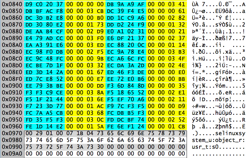
Let’s examine block 8460516 which holds the extent information. Here are the first 256 bytes in a hex editor:
0-3     Magic number                        BMA3
4-5     Level in tree                       0 (leaf node)
6-7     Number of extents                   42
8-15    Left sibling pointer                -1 (NULL)

16-23   Right sibling pointer               -1 (NULL)
24-31   Sector offset of this block         0x02595720 = 39409440

32-39   LSN of last update                  0x200000631b
40-55   UUID                                e56c...da71
56-63   Inode owner of this block           0x022f4d7d = 36654461

64-67   CRC32 of this block                 0x9d14d936
68-71   Padding for 64-bit alignment        zeroed
This node is at level zero in the tree, which means it’s a leaf node containing data. In this case the data is extent structures, and there are 42 of them following the header.
If there were more than one leaf node, the left and right sibling pointers would be used. Since we only have the one leaf, both of these values are set to -1, which is used as a NULL pointer in XFS metadata structures.
As far as decoding the extent structures, it’s easier to use xfs_db:
As we saw in the previous installment, multi-block directories in XFS are sparse files:
Starting at logical offset zero, we have extents 1-33 containing the first 35 blocks of the directory file. This is where the directory entries live.
Extents 34-41 starting at logical offset 8388608 (XFS_DIR2_LEAF_OFFSET) contain the hash lookup table for finding directory entries.
Because the hash lookup table is large enough to require multiple blocks, the “tail record” for the directory moves into its own block tracked by the final extent (extent 42 in our example above). The logical offset for the tail record is 2*XFS_DIR2_LEAF_OFFSET or 16777216.
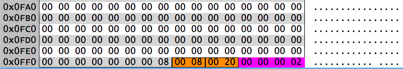
The Tail Record
0-3      Magic number                       XDF3
4-7      CRC32 checksum                     0xf56e9aba
8-15     Sector offset of this block        22517032

16-23    Last LSN update                    0x200000631b
24-39    UUID                               e56c...da71
40-47    Inode that points to this block    0x022f4d7d

48-51    Starting block offset              0
52-55    Size of array                      35
56-59    Array entries used                 35
60-63    Padding for 64-bit alignment       zeroed
The last two fields describe an array whose elements correspond to the blocks in the hash lookup table for this directory. The array itself follows immediately after the header as shown above. Each element of the array is a two-byte number representing the largest chunk of free space available in each block. In our example, all of the blocks are full (zero free bytes) except for the last block which has at least a 0x0440 = 1088 byte chunk available.
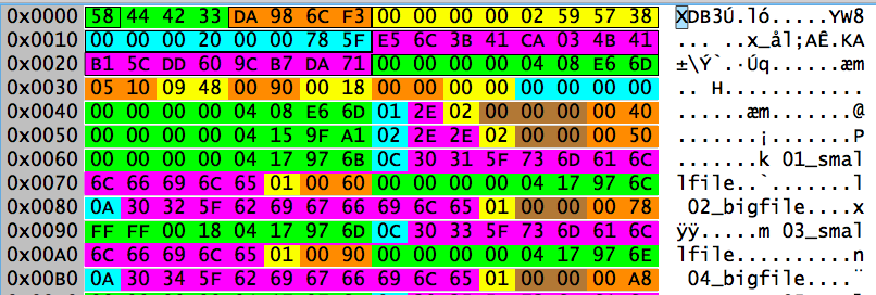
Decoding the Hash Lookup Table
The hash lookup table for this directory is contained in the fifteen blocks starting at logical file offset 8388608. Because the hash lookup table spans multiple blocks, it is also formatted as a B+Tree. The initial block at logical offset 8388608 should be the root of this tree. This block is shown below.
0-3      "Forward" pointer                  0
4-7      "Back" pointer                     0
8-9      Magic number                       0x3ebe
10-11    Padding for alignment              zeroed
12-15    CRC32 checksum                     0x129cf461

16-23    Sector offset of this block        22517064
24-31    LSN of last update                 0x200000631b

32-47    UUID                               e56c...da71

48-55    Parent inode                       0x022f4d7d
56-57    Number of array entries            14
58-59    Level in tree                      1
59-63    Padding for alignment              zeroed
We confirm this is an interior node of a B+Tree by looking at the “Level in tree” value at bytes 58-59– interior nodes have non-zero values here. The “forward” and “back” pointers being zeroed mean there are no other nodes at this level, so we’re sitting at the root of the tree.
The fourteen other blocks that hold the directory entries are tracked by an array here in the root block. Bytes 56-57 track the size of the array, and the array itself starts at byte 64. Each array entry contains a four byte hash value and a four byte logical block offset. The hash value in each array entry is the largest hash value in the given block.
If you look at the residual data in the block after the hash array, it looks like hash values and block offsets similar to what we’ve seen in previous installments. I speculate that this is residual data from when the hash lookup table was able to fit into a single block. Once the directory grew to a point where the B+Tree was necessary, the new B+Tree root node simply took over this block, leaving a significant amount of residual data in the slack space.
To understand the function of the leaf nodes in the B+Tree, suppose we wanted to find the directory entry for the file “0003_smallfile”. First we can use xfs_db to compute the hash value for this filename:
xfs_db> hash 0003_smallfile
0xbc07fded
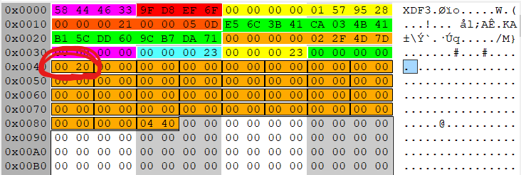
According to the array, that hash value should be in logical block 8388614. We then have to refer back to the list of extents we decoded earlier to discover that this local offset corresponds to block address 8460517 (AG 2, block 71909). Here is the breakdown of that block:
0-3      Forward pointer                    0x800001 = 8388609
4-7      Back pointer                       0x800008 = 8388616
8-9      Magic number                       0x3dff
10-11    Padding for alignment              zeroed
12-15    CRC32 checksum                     0xdb227061

16-23    Sector offset of this block        39409448
24-31    LSN of last update                 0x200000631b

32-47    UUID                               e56c...da71

48-55    Parent inode                       0x022f4d7d
56-57    Number of array entries            0x01a0 = 416
58-59    Unused entries                     0
59-63    Padding for alignment              zeroed
Following the 64-byte header is an array holding the hash lookup structures. Each structure contains a four byte hash value and a four byte offset. The array is sorted by hash value for binary search. Offsets are in 8 byte units.
The has value for “0003_smallfile” was 0xbc07fded. We have to look fairly far down in the array to find the offset for this value:
The offset tells us that the directory entry of “0003_smallfile” should be 0x13 = 19 * 8 = 152 bytes from the start of the directory file. That puts it near the beginning of the first block at logical offset zero.
The Directory Entries
To find the first block of the directory file we need to refer back to the extent list we decoded from the inode at the very start of this article. According to that list, the initial block is 4581802 (AG 1, block 387498). Let’s take a closer look at this block:
0-3      Magic number                       XDD3
4-7      CRC32 checksum                     0xaf173b31
8-15     Sector offset to this block        22517072

16-23    LSN of last update                 0x200000631b
24-39    UUID                               e56c...da71
40-47    Parent inode                       0x022f4d7d
Bytes 48-59 are a three element array indicating where there is available free space in this directory. Each array element is a 2 byte offset (in bytes) to the free space and a 2 byte length (in bytes). There is no free space in this block, so all array entries are zeroed. Bytes 60-63 are padding for alignment.
Following this header are variable length directory entries defined as follows:
     Len (bytes)     Field
     ===========     ======
       8             absolute inode number
       1             file name length (bytes)
       varies        file name
       1             file type
       varies        padding as necessary for 64bit alignment
       2             offset to beginning of this entry
Here is the decoding of the directory entries shown above:
File type bytes are as described in Part Three of this series (1 is a regular file, 2 is a directory). Note that the starting offset of the “0003_smallfile” entry is 152 bytes (0x0098), exactly as the hash table lookup told us.
What Happens Upon Deletion?
Let’s see what happens when we delete “0003_smallfile”. When doing this sort of testing, always be careful to force the file system cache to flush to disk before busting out the trusty hex editor:
The mtime and ctime in the directory inode are set to the deletion time of “0003_smallfile”. The LSN and CRC32 checksum in the inode are also updated.
The removal of a single file is typically not a big enough event to modify the size of the directory. In this case, neither the extent tree root or leaf block changes. We would have to purge a significant number of files the impact this data.
However, the “tail record” for the directory is impacted by the file deletion.
The CRC32 checksum and LSN (now highlighted in red) are updated. Also the free space array now shows 0x20 = 32 bytes free in the first block.
Again, a single file deletion is not significant enough to impact the root of the hash B+Tree. However, one of the leaf nodes does register the change.
Again we see updates to the CRC32 checksum and LSN fields. The “Unused entries” field for the hash array now shows one unused entry. Looking farther down in the block, we find the unused entry for our hash 0xbc07fded. The offset is zeroed to indicate this entry is unused. We saw similar behavior in other block-based directories in previous installments of this series.
Changes to the directory entries are also similar to the behavior we’ve seen previously for block-based directory files:
Again we see the usual CRC32 and LSN updates. But now the free space array starting at byte 48 shows 0x0020 = 32 bytes free at offset 0x0098 = 152. The first two bytes of the inode field in this directory are overwritten with 0xFFFF to indicate the unused space, and the next two bytes indicate 0x0020 = 32 bytes of free space. However, since the inodes in this file system fit in 32 bits, the original inode number for the file is still fully visible and the file could potentially be recovered using residual data in the inode.
Wrapping Up and Planning for the Future
This post concludes my walk-through of the major on-disk data structures in the XFS file system. If anything was unclear or you want more detailed explanations in any area, feel free to reach me through the comments or via any of my social media accounts.
The colorized hex dumps that appear in these posts where made with a combination of Synalize It! and Hexinator. Along the way I created “grammar” files that you can use to produce similar colored breakdowns on your own XFS data structures.
I have multiple pages of research questions that came up as I was working through this series. But what I’m most interested in at the moment is the process of recovering deleted data from XFS file systems. This is what I will be looking at in upcoming posts.
I’ve removed much of the output here to make things more readable. The directory file is fragmented, requiring multiple single-block extents, which is common for directories in XFS. The directory would start as a single block. Eventually enough files will be added to the directory that it needs more than one block to hold all the file entries. But by this time, the blocks immediately following the original directory block have been consumed– often by the files which make up the content of the directory. When the directory needs to grow, it typically has to fragment.
What is really interesting about multi-block directories in XFS is that they are sparse files. Looking at the list of extents at the end of the xfs_db output, we see that the first two blocks are at logical block offsets 0 and 1, but the third block is at logical block offset 8388608. What the heck is going on here?
If you recall from our discussion of block directories in the last installment, XFS directories have a hash lookup table at the end for faster searching. When a directory consumes multiple blocks, the hash lookup table and “tail record” move into their own block. For consistency, XFS places this information at logical offset XFS_DIR2_LEAF_OFFSET, which is currently set to 32GB. 32GB divided by our 4K block size gives a logical block offset of 8388608.
From a file size perspective, we can see that xfs_db agrees with our earlier ls output, saying the directory is 8192 bytes. However, the xfs_db output clearly shows that the directory consumes three blocks, which should give it a file size of 3*4096 = 12288 bytes. Based on my testing, the directory “size” in XFS only counts the blocks that contain directory entries.
We can use xfs_db to examine the directory data blocks in more detail:
I’m using the addr command in xfs_db to select the startblock value from the first extent in the array (the zero element of the array).
The beginning of this first data block is nearly identical to the block directories we looked at previously. The only difference is that single block directories have a magic number “XDB3”, while data blocks in multi-block directories use “XDD3” as we see here. Remember that the value that xfs_db lobels dhdr.hdr.bno is actually the sector offset to this block and not the block number.
Again we see the same header information. Note that each data block has it’s own “free space” array, tracking available space in that data block.
Finally, we have the block containing the hash lookup table and tail record. We could use xfs_db to decode this block, but it turns out that there are some interesting internal structures to see here. Here’s the hex editor view of the start of the block:
:
0-3     Forward link                        0
4-7     Backward link                       0
8-9     Magic number                        0x3df1
10-11   Padding                             zeroed
12-15   CRC32                               0xef654461

16-23   Sector offset                       38883440
24-31   Log seq number last update          0x2200008720
32-47   UUID                                e56c3b41-...-dd609cb7da71
48-55   Inode number                        67146849

56-57   Number of entries                   0x0126 = 294
58-59   Unused entries                      1
60-63   Padding for alignment               zeroed
The “forward” and “backward” links would come into play if this were a multi-node B+Tree data structure rather than a single block. Unlike previous magic number values, the magic value here (0x3df1) does not correspond to printable ASCII characters.
After the typical XFS header information, there is a two-byte value tracking the number of entries in the directory, and therefore the number of entries in the hash lookup table that follows. The next two bytes tell us that there is one unused entry– typically a record for a deleted file.
We find this unused record near the end of the hash lookup array. The entry starting at block offset 0x840 has an offset value of zero, indicating the entry is unused:
Interestingly, right after the end of the hash lookup array, we see what appears to be the extended attribute information from an inode. This is apparently residual data left over from an earlier use of the block.
At the end of the block is data which tracks free space in the directory:
The last four bytes in the block are the number of blocks containing directory entries– two in this case. Preceding those four bytes is a “best free” array that tracks the length of the largest chunk of free space in each block. You will notice that the array values here correspond to the dhdr.bestfree[0].length values for each block in the xfs_db output above. When new directory entries are added, this array helps the file system locate the best spot to place the new entry.
We see the two bytes immediately before the “best free” array are identical to the first entry in the array. Did the /etc directory once consume three blocks and later shrink back to two? Based on limited testing, this appears to be the case. Unlike directories in traditional Unix file systems, which never shrink once blocks have been allocated, XFS directories will grow and shrink dynamically as needed.
So far we’ve looked at the three most common directory types in XFS: small “short form” directories stored in the inode, single block directories, and in this case a multi-block directories tracked with an extent array in the inode. In rare cases, when the directory is very large and very fragmented, the extent array in the inode is insufficient. In these cases, XFS uses a B+Tree to track the extent information. We will examine this scenario in the next installment.
In the previous installment, we looked at small directories stored in “short form” in the inode. While these small directories can make up as much as 90% of the total directories in a typical Linux file system, eventually directories get big enough that they can no longer be packed into the inode data fork. When this happens, directory data moves out to blocks on disk.
In the inode, the data fork type (byte 5) changes to indicate that the data is no longer stored within the inode. Extents are used to track the location of the disk blocks containing the directory data. Here is the inode core and extent list for a directory that only occupies a single block:
The data fork type is 2, indicating an extent list follows the inode core. Bytes 76-79 indicate that there is only a single extent. The extent starts at byte 176 (0x0B0), immediately after the inode core. The last 21 bits of the extent structure show that the extent only contains a single block. Parsing the rest of the extent yields a block address of 0x8118e7, or relative block 71911 in AG 2.
We can extract this block and examine it in our hex editor. Here is the data in the beginning of the block:
The directory block begins with a 48 byte header:
0-3      Magic number                       XDB3
4-7      CRC32 checksum                     0xaf6a416d
8-15     Sector offset of this block        39409464

16-23    Last LSN update                    0x20000061fe
24-39    UUID                               e56c3b41-...-dd609cb7da71
40-47    inode that points to this block    0x0408e66d
You may compare the UUID and inode values in the directory block header with the corresponding values in the inode to see that they match.
The XFS documentation describes the sector offset field as the “block number”. However, using the formula from Part 1 of this series, we can calculate the physical block number of this block as:
Multiply the block offset 4926183 by 8 sectors per block to get the sector offset value 39409464 that we see in the directory block header.
Following the header is a “free space” array that consumes 12 bytes, plus 4 bytes of padding to preserve 64-bit alignment. The free space array contains three elements which indicate where the three largest chunks of unused space are located in this directory block. Each element is a 2 byte offset and a 2 byte length field. The elements of the array are sorted in descending order by the length of each chunk.
In this directory block, there is only a single chunk of free space, starting at offset 1296 (0x0510) and having 2376 bytes (0x0948) of space. The other elements of the free space array are zeroed, indicating no other free space is available.
The directory entries start at byte 64 (0x040) and can be read sequentially like a typical Unix directory. However, XFS uses a hash-based lookup table, growing up from the bottom of the directory block, for more efficient searching:
The last 8 bytes of the directory block are a “tail record” containing two 4 byte values: the number of directory entries (0x34 or 52) and the number of unused entries (zero). Immediately preceding the tail record will be an array of 8 byte records, one record per directory entry (52 records in this case). Each record contains a hash value computed from the file name, and the offset in the directory block where the directory entry for that file is located. The array is sorted by hash value so that binary search can quickly find the desired record. The offsets are in 8 byte units.
The xfs_db program can compute hash values for us:
xfs_db> hash 03_smallfile
0x3f07fdec
If we locate this hash value in the array, we see the byte offset value is 0x12 or 18. Since the offset units are 8 bytes, this translates to byte offset 144 (0x090) from the start of the directory block.
Here are the first six directory entries from this block, including the entry for “03_smallfile”:
Directory entries are variable length, but always 8 byte (64-bit) aligned. The fields in each directory entry are:
     Len (bytes)       Field
     ===========       =====
          8            Inode number
          1            File name length
          varies       File name
          1            File type
          varies       Padding for alignment
          2            Byte offset of this directory entry
64-bit inode addresses are always used. This is different from “short form” directories, where 32-bit inode addresses will be used if possible.
File name length is a single byte, limiting file names to 255 characters. The file type byte uses the same numbering scheme we saw in “short form” directories:
    1   Regular file
    2   Directory
    3   Character special device
    4   Block special device
    5   FIFO
    6   Socket
    7   Symlink
Padding for alignment is only included if necessary. Our “03_smallfile” entry starting at offset 0x090 is exactly 24 bytes long and needs no padding for alignment. You can clearly see the padding in the “.” and “..” entries starting at offset 0x040 and 0x050 respectively.
Deleting a File
If we remove “03_smallfile” from this directory, the inode updates similarly to what we saw with the “short form” directory in the last installment of this series. The mtime and ctime values are updated, and the CRC32 and Logfile Sequence Number fields as well. The file size does not change, since the directory still occupies one block.
The “tail record” and hash array at the end of the directory block change:
The tail record still shows 34 entries, but one of them is now unused. If we look at the entry for hash 0x3F07FDEC, we see the offset value has been zeroed, indicating an unused record.
We also see changes at the beginning of the block:
The free space array now uses the second element, showing 24 (0x18) bytes free at byte offset 0x90– the location where the “03_smallfile” entry used to reside.
Looking at offset 0x90, we see that the first two bytes of the inode field are overwritten with 0xFFFF, indicating an unused entry. The next two bytes are the length of the free space. Again we see 0x18, or 24 bytes.
However, since inode addresses in this file system fit in 32 bits, the original inode address associated with this file is still clearly visible. The rest of the original directory entry is untouched until a new entry overwrites this space. This should make file recovery easier.
Not Quite Done With Directories
When directories get large enough to occupy multiple blocks, the directory structure gets more complicated. We’ll examine larger directories in our next installment.
XFS uses several different directory structures depending on the size of the directory. For testing purposes, I created three directories– one with 5 files, one with 50, and one with 5000 file entries. Small directories have their data stored in the inode. In this installment we’ll examine the inode of the directory that contains only five files.
We documented the “inode core” layout and the format of the extended attributes in Part 2 of this series. In this inode the file type (upper nibble of byte 2) is 4, which means it’s a directory. The data fork type (byte 5) is 1, meaning resident data.
Resident directory data is stored as a “short form” directory structure starting at byte offset 176, right after the inode core. First we have a brief header:
176      Number of directory entries                   5
177      Number of dir entries needing 64-bit inodes   0
178-181  Inode of parent                               0x04159fa1
First we have a byte tracking the number of directory entries to follow the header. The next byte tracks how many directory entries require 64 bits for inode data. As we saw in Part 1 of this series, XFS uses variable length addreses for blocks and inodes. In our file system, we need less than 32 bits to store these addresses, so there are no directory entries requiring 64-bit inodes. This means the directory data will use 32 bits to store inodes in order to save space.
This has an immediate impact because the next entry in the header is the inode of the parent directory. Since byte 177 is zero, this field will be 32 bits. If byte 177 was non-zero, then all inode entries in the header and directory entries would be 64-bit.
The parent inode field in the header is the equivalent of the usual “..” link in the directory. The current directory inode (the “.” link) is found in the inode core in bytes 152-159. The short form directory simply uses these values and does not have explicit “.” and “..” entries.
After the header come a series of variable length directory entries, packed as tightly as possible with no alignment constraints. Entries are added to the directory in order of file creation and are not sorted in any way.
Here is a description of the fields and a breakdown of the values in the five directories in this inode:
      Len (Bytes)      Field
          1            Length of file name (in bytes)
          2            Entry offset in non short form directory
          varies       Characters in file name
          1            File type
          4 or 8       Absolute inode address

Len    Offset     Name            Type      Inode
===    ======     ====            ====      =====
12     0x0060     01_smallfile    01        0x0417979d
10     0x0078     02_bigfile      01        0x0417979e
12     0x0090     03_smallfile    01        0x0417979f
10     0x00a8     04_bigfile      01        0x0417a154
12     0x00c0     05_smallfile    01        0x0417a155
First we have a single byte for the file name length in bytes. Like other Unix file systems, there is a 255 character file name limit.
The next two bytes are based on the byte offset the directory entry would have if it were a normal XFS directory entry and not packed into a short form directory in the inode. In a normal directory block, directory entries are 64-bit aligned and start at byte offset 96 (0x60) following the directory header and “.” and “..” entries. The directory entries here are all 18 or 20 bytes long, which means they would consume 24 bytes (0x18) in a normal directory block. Using a consistent numbering scheme for the offset makes it easier to write code that iterates through directory entries, even though the offsets don’t match the actual offset of each directory entry in the short form style.
Next we have the characters in the file name followed by a single byte for the file type. The file type is included in the directory entry so that commands like “ls -F” don’t have to open each inode to get the file type information. The file type values in the directory entry do not use the same number scheme as the file type in the inode. Here are the expected values for directory entries:
    1   Regular file
    2   Directory
    3   Character special device
    4   Block special device
    5   FIFO
    6   Socket
    7   Symlink
Finally there is a field to hold the inode associated with the file name. In our example, these inode entries are 32 bits. 64-bit inode fields will be used if the directory header indicates they are needed.
Deleting a File
When a file is deleted from (or added to) a directory, the mtime and ctime in the directory’s inode core are updated. The directory file size changes (bytes 56-63). The CRC32 checksum and the logfile sequence number fields are updated.
In the data fork, all directory entries after the deleted entry are shifted downwards, completely overwriting the deleted entry. Here’s what the directory entries look like after “03_smallfile”– the third entry in the original directory– is deleted:
The four remaining directory entries are highlighted above. However, after those entries you can clearly see the residue of the entry for “05_smallfile” from the original directory. So as short-form directories shrink, they leave behind entries in the unused “inode slack”. In this case the residue is for a file entry that still exists in the directory, but it’s possible that we might get residue of entries deleted from the end of the directory list.
When Directories Grow Up
Another place you can see short form directory residue is when the directory gets large enough that it needs to move out to blocks on disk. I created a sample directory that initially had five files and confirmed that it was being stored as a short form directory in the inode. Then I added 45 more files to the directory, which made a short form directory impossible. Here’s what the first part of the inode looks like after these two operations:
The data fork type (byte 5) is 2, meaning an extent list after the inode core, giving the location of the directory content on disk. You can see the extent highlighted starting at byte offset 176 (0xb0). But immediately after that extent you can see the residue of the original short-form directory.
The format of directories changes significantly when directory entries move out into disk blocks. In our next installment we will examine the structures in these larger directories.
Part 1 of this series was a quick introduction to XFS, the XFS superblock, and the unique Allocation Group (AG) based addressing scheme used in the file system. With this information, we were able to extract an inode from its physical location on disk
In this installment, we will look at the structure of the XFS inode. Since we will want to see what remains in the inode after a file is deleted, I’m going to create a small file for testing purposes:
[root@localhost ~]# echo This is a small file >testfile
[root@localhost ~]# ls -i testfile
100799719 testfile
To save time, we’ll use the xfs_db program to convert that inode address into the values we need to extract the inode from its physical location on disk. Then we’ll use dd to extract the inode as we did in Part 1.
We can now view the inode in our trusty hex editor:
XFS v5 inodes start with a 176 byte “inode core” structure:
0-1      Magic number                              "IN"
2-3      File type and mode bits (see below)       1000 000 110 100 100
4        Version (v5 file system uses v3 inodes)   3
5        Data fork type flag (see below)           2
6-7      v1 inode numlinks field (not used in v3)  zeroed
8-11     File owner UID                            0 (root)
12-15    File GID                                  0 (root)

16-19    v2+ number of links                       1
20-21    Project ID (low)                          0
22-23    Project ID (high)                         0
24-29    Padding (must be zero)                    0
30-31    Increment on flush                        0

32-35    atime epoch seconds                       0x5afdd6cd
36-39    atime nanoseconds                         0x2467330e
40-43    mtime epoch seconds                       0x5afdd6cd
44-47    mtime nanoseconds                         0x24767568

48-51    ctime epoch seconds                       0x5afd d6cd
52-55    ctime nanoseconds                         0x2476 7568
56-63    File (data fork) size                     0x15 = 21

64-71    Number of blocks in data fork             1
72-75    Extent size hint                          zeroed
76-79    Number of data extents used               1

80-81    Number of extended attribute extents      0
82       Inode offset to xattr (8 byte multiples)  0x23 = 35 * 8 = 280
83       Extended attribute type flag (see below)  1
84-87    DMAPI event mask                          0
88-89    DMAPI state                               0
90-91    Flags                                     0 (none set)
92-95    Generation number                         0xa3fd42cd

96-99    Next unlinked ptr (if inode unlinked)    -1 (NULL in XFS)

/* v3 inodes (v5 file system) have the following fields */
100-103  CRC32 checksum for inode                  0xb43f0d10
104-111  Number of changes to attributes           1

112-119  Log sequence number of last update        0x2100006185
120-127  Extended flags                            0 (none set)

128-131  Copy on write extent size hint            0
132-143  Padding for future use                    0

144-147  btime epoch seconds                       0x5afdd6cd
148-151  btime nanoseconds                         0x2467330e
152-159  inode number of this inode                0x60214e7 = 100799719

160-175  UUID                                      e56c3b41-...-dd609cb7da71
XFS inodes start with the 2 byte magic number value “IN”. Inodes also have a CRC32 checksum (bytes 100-103) to help detect corruption. The inode includes its own absolute inode number (bytes 152-159) and the file system UUID (bytes 160-175), which should match the UUID value from the superblock. Whenever the inode is updated, bytes 112-119 track the “logfile sequence number” (LSN) of the journal entry for the update. The inode format has changed across different versions of the XFS file system, so refer to the inode version in byte 4 before decoding the inode. XFS v5 uses v3 inodes.
The size of the file (in bytes) is a 64-bit value in bytes 56-63. The original XFS inode tracked the number of links as a 16-bit value (bytes 6-7), which is no longer used. Number of links is now tracked as a 32-bit value found in bytes 16-19.
Timestamps include both a 32-bit “Unix epoch” style seconds field and a 32-bit nanosecond resolution fractional seconds field. The three classic Unix timestamps– atime, mtime, ctime– are found in bytes 32-55 of the inode. File creation time (btime) was only added in XFS v5, so that timestamp resides in bytes 144-151 in the upper portion of the inode core.
File ownership and permissions are tracked as in earlier Unix file systems. There are 32-bit file owner (bytes 8-11) and group owner (bytes 12-15) fields. File type and permissions are stored in a packed 16-bit structure. The low 12 bits are the standard Unix permissions bits, and the upper four bits are used for the file type.
The file type nibble will be one of the following values:
   8   Regular file
   4   Directory
   2   Character special device
   6   Block special device
   1   FIFO
   C   Socket
   A   Symlink
The 12 permissions bits are grouped into four groups of 3 bits, and are often written in octal notation– in our case we have 0644. The first group of three represents the “special” bit flags: set-UID, set-GID, and “sticky” (none of these are set for our test file). The remaining three groups represent “read” (r), “write” (w), and “execute” (x) permissions for three categories. The first set of bits applies to the file owner, the second to members of the Unix group that owns the file, and the last group for everybody else. The permissions on our test file are 644 or 110 100 100 aka rw-r–r–. In other words, read and write access for the file owner, and read only access for group members and for all other users on the system.
The remaining space after the 176 bytes of inode core is used to track the data blocks associated with the file (the “data fork” of the file) and any extended attributes that may be set. There are multiple ways in which data and attributes may be stored– locally resident within the inode, in a series of extents, or in a more complex B+Tree indexed structure. The data fork type flag in byte 5 and the extended attribute type flag in byte 83 document how this information is organized. The possible values for these fields are:
   0   Special device file (data type only)
   1   Data is resident ("local") in the inode
   2   Array of extent structures follows
   3   B+Tree root follows
Currently XFS only uses resident or “local” storage for extended attributes and small directories. There is a proposal to allow small files to be stored in the inode (similar to NTFS), but this is still under development. The data fork for our small test file is type 2– an array of extent structures. The extended attributes are type 1, meaning they are stored locally in the inode.
The data fork starts at byte 176, immediately after the inode core. The start of the extended attribute data is found at an offset from the end of the inode core. This offset is byte 82 of the inode core, and the units are multiples of 8 bytes. In our sample inode, the offset value is 0x23 or 35. Multiplying by 8 gives a byte offset of 280 from the end of the inode core, or 176+280=456 bytes from the beginning of the inode.
Extent Arrays
The most common storage option for file content in XFS is data fork type 2– an array of 16 byte extent structures starting immediately after the inode core. Bytes 76-79 indicate how many extent structures are in the array. Our file is not fragmented, so there is only a single extent structure in the inode.
Theoretically, the 336 bytes following the inode core could hold 21 extent structures, assuming no extended attribute data. If the inode cannot hold all of the extent information (an extremely fragmented file), then the data fork in the inode becomes the root of a B+Tree (data fork type 3) for tracking extent information. We will see an example of this in a later installment in this series.
The challenging thing about XFS extent structures is that they are not byte aligned. They contain four fields as follows:
Flag (1 bit) – Set if extent is preallocated but not yet written, zero otherwise
Logical offset (54 bits) – Logical offset from the start of the file
Starting block (52 bits) – Absolute block address of the start of the extent
Length (21 bits) – Number of blocks in the extent
If you think this makes manually decoding XFS extent information challenging, you’d be correct. Let’s break the extent structure down into individual bits in order to make decoding a bit easier. The extent starts at byte offset 176 (0xb0), and I’ll use a little command-line magic to see the bits:
Let’s check and see if we decoded the structure correctly:
[root@localhost ~]# dd if=/dev/mapper/centos-root bs=4096
                       skip=$((3*2427136 + 16505)) count=1 | xxd
0000000: 5468 6973 2069 7320 6120 736d 616c 6c20  This is a small
0000010: 6669 6c65 0a00 0000 0000 0000 0000 0000  file............
0000020: 0000 0000 0000 0000 0000 0000 0000 0000  ................
0000030: 0000 0000 0000 0000 0000 0000 0000 0000  ................
[... all zeroes to end ...]
Looks like we got it right. Note that XFS null fills file slack space, which is typical for Unix file systems.
Extended Attributes
XFS allows arbitrary extended attributes to be added to the file. Attributes are simply name, value pairs. There is a 255 byte limit on the size of any attribute name or value. You can set or view attributes from the command line with the “attr” command.
If the amount of attribute data is small, extended attributes will be stored in the inode, just as they are in our sample file. Large amounts of attribute information may need to be stored in data blocks on disk, in which case the attribute data is tracked using extents just like the data fork.
As we discussed above, resident attribute information starts at a specific byte offset from the end of the inode core. In our sample file the offset is 280 bytes from the end of the inode core or 456 bytes (280 + 176) from the start of the inode.
Attributes start with a four byte header:
456-457  Length of attributes               0x34 = 52
458      Number of attributes to follow     1
459      Padding for alignment              0
The length field unit is bytes and includes the 4 byte header. Our sample file only contains a single attribute.
Each attribute structure is variable length, to allow attributes to be packed as tightly as possible. Each attribute structure starts with a single byte for the name length, then a byte for the value length, and a flag byte. The rest of the attribute structure is the name followed by the value, with no null terminators or padding for byte alignment.
Breaking down the single attribute we have in our sample inode, we see:
460      Length of name                     7
461      Length of value                    0x26 = 38
462      Flags                              4
463-469  Attribute name                     selinux
470-507  Attribute value                    unconfined_u:...
This attribute holds the SELinux context on our file, “unconfined_u:object_r:admin_home_t:s0”. While extended attribute values are not required to be null-terminated, SELinux expects it’s context labels to have null terminators. So the 38 byte value length is 37 printable characters and a null.
The flags field is designed to control access to the attribute information. The flags byte is defined as a bit mask, but only four values appear to be used currently:
   128   Attribute is being updated
     4   "Secure" - attribute may be viewed by all but only set by root
     2   "Trusted" - attribute may only be viewed and set by root
     0   No restrictions
The Inode After Deletion
When a file is deleted, changes are limited to a small number of fields in the inode core:
The 2 byte file type and permissions field is zeroed
Link count, file size, number of blocks, and number of extents are zeroed
ctime is set to the time the file was deleted
The offset to the extended attributes is zeroed
The data fork and extended attribute type bytes are set to 2, which would normally mean an extent array
The “Generation number” field (inode bytes 92-95) is incremented–more testing is required, but it appears this field may be a usage count for the inode
The CRC32 checksum and the LSN are updated
No other data in the inode changes. So while the number of extents value is zeroed and so is the offset to the start of the extended attributes, the actual extent and attribute data remains in the inode.
This means it should be straightforward to recover the original file by parsing whatever extent data exists starting at inode offset 176. The XFS FAQ points to two Open Source projects that appear to use this idea to recover deleted files, and a little Google searching turns up several commercial tools that claim to do XFS file recovery:
I have not had the opportunity to test any of these tools.
In limited testing it also appears that the data fork and the extended attribute information are not zeroed when the inode is reused. This means there is the possibility of finding remnants of data from a previous file in the unused or “slack” space in the inode.
Using xfs_db to View Inodes
xfs_db allows you to quickly view the inode values, even for inodes that are currently unallocated:
xfs_db even converts the timestamps for you, so that’s a win.
What’s Next?
XFS does not store file name information in the inode, which is pretty typical for Unix file systems. The only place where file names exist is in directory entries. In our next installment we will begin to examine the different XFS directory types. Yes, it’s complicated.
The XFS file system was originally developed by Silicon Graphics for their IRIX operating system. The Linux version is increasingly popular– Red Hat has adopted XFS as their default file system as of Red Hat Enterprise Linux v7. Unfortunately, while XFS is becoming more common on Linux systems, we are lacking forensic tools for decoding this file system. This series will provide insights into the XFS file system structures for forensics professionals, and document the current state of the art as far as tools for decoding XFS.
I would like to thank the XFS development community for their work on the file system and their help in preparing these articles. Links to the documentation, source code, and the mailing list are available from XFS.org. I wouldn’t have been able to do any of this work without these resources.
A Quick Overview of XFS
XFS is a modern journaled file system which uses extent-based file allocation and B+Tree style directories. XFS supports arbitrary extended file attributes. Inodes are dynamically allocated. The block size is 4K by default, but can be set to other values at file system creation time. All file system metadata is stored in “big endian” format, regardless of processor architecture.
Some of the structures in XFS are recognizable from older Unix file systems. XFS still uses 32-bit signed Unix epoch style timestamps, and has the “Year 2038” rollover problem as a result. XFS v5– the version currently used in Linux– does have a creation date (btime) field in addition to the normal last modified (mtime), access time (atime), and metadata change time (ctime) timestamps. XFS timestamps also have an additional 32-bit nanosecond resolution element. File type and permissions are stored in a packed 16-bit value, just like in older Unix file systems.
Very little data gets overwritten when files are deleted in XFS. Directory entries are simply marked as unused, and the extent data in the inode is still visible after deletion. File recovery should be straightforward.
In addition, standard metadata structures in XFS v5 contain a consistent unique file system UUID value, along with information like the inode value associated with the data structure. Metadata structures also have unique “magic number” values. These features facilitate file system and data recovery, and are very useful when carving or viewing raw file system data. Metadata structures include a CRC32 checksum to help detect corruption.
One interesting feature of XFS is that a single file system is subdivided into multiple Allocation Groups— four by default on RHEL systems. Each allocation group (AG) can be treated as a separate file system with its own inode and block lists. The intention was to allow multiple threads to write in parallel to the same file system with minimal interaction. This makes XFS a quite high performing file system on multi-core systems.
It also leads to a unique addressing scheme for blocks and inodes that uses a combination of the AG number and a relative block or inode offset within that AG. These values are packed together into a single address, normally stored as a 64-bit value. However the actual length of the relative portion of the address and the AG value can vary from file system to file system, as we will discuss below. In other words, it’s complicated.
The Superblock
As with other Unix file systems, XFS starts with a superblock which helps decode the file system. The superblock occupies the first 512 bytes of each XFS AG. The primary superblock is the one in AG 0 at the front of the file system, with the superblocks in the other AGs used for redundancy.
Only the first 272 bytes of the superblock are currently used. Here is a breakdown of the information from the superblock:
0-3      Magic Number                       "XFSB"
4-7      Block Size (in bytes)              0x1000 = 4096
8-15     Total blocks in file system        0x942400 = 9,708,544

16-23    Num blocks in real-time device     zeroed
24-31    Num extents in real-time device    zeroed

32-47    UUID                               e56c3b41-...-dd609cb7da71

48-55    First block of journal             0x800004 = 8388612
56-63    Root directory's inode             0x40 = 64

64-71    Real-time extents bitmap inode     0x41 = 65
72-79    Real-time bitmap summary inode     0x42 = 66

80-83    Real-time extent size (in blocks)  0x01
84-87    AG size (in blocks)                0x250900 = 2,427,136 (c.f. 8-15)
88-91    Number of AGs                      0x04
92-95    Num of real-time bitmap blocks     zeroed

96-99    Num of journal blocks              0x1284 = 4740
100-101  File system version and flags      0xB4B5 (low nibble is version)
102-103  Sector size                        0x200 = 512
104-105  Inode size                         0x200 = 512
106-107  Inodes/block                       0x08
108-119  File system name                   not set-- zeroed
120      log2(block size)                   0x0C (2^^12 = 4096)
121      log2(sector size)                  0x09 (2^^9 = 512)
122      log2(inode size)                   0x09
123      log2(inode/block)                  0x03 (2^^3 = 8 inode/block)
124      log2(AG size) rounded up           0x16 (2^^22 = 4M > 2,437,136)
125      log2(real-time extents)            zeroed
126      File system being created flag     zeroed
127      Max inode percentage               0x19 = 25%

128-135  Number of allocated inodes         0x2C500 = 181504
136-143  Number of free inodes              0x385 = 901

144-151  Number of free blocks              0x8450dc = 8,671,452
152-159  Number of free real-time extents   zeroed

160-167  User quota inode                   -1 (NULL in XFS)
168-175  Group quota inode                  -1 (NULL in XFS)

176-177  Quota flags                        zero
178      Misc flags                         zero
179      Reserved                           Must be zero
180-183  Inode alignment (in blocks)        0x04
184-187  RAID unit (in blocks)              zeroed
188-191  RAID stripe (in blocks)            zeroed

192      log2(dir blk allocation granularity)         zero
193      log2(sector size of externl journal device)  zero
194-195  Sector size of external journal device       zero
196-199  Stripe/unit size of external journal device  0x01
200-203  Additional flags                             0x018A
204-207  Repeat additional flags (for alignment)      0x018A

/* Version 5 only */
208-211  Read-write feature flags (not used)          zero
212-215  Read-only feature flags                      zero
216-219  Read-write incompatibility flags             0x01
220-223  Read-write incompat flags for log (unused)   zero

224-227  CRC32 checksum for superblock                0x0A5832D0
228-231  Sparse inode alignment                       zero
232-239  Project quota inode                          -1

240-247  Log seq number of last superblock update     0x19000036EA
248-263  UUID used if INCOMPAT_META_UUID feature      zeroed
264-271  If INCOMPAT_META_RMAPBT, inode of RM btree   zeroed
Rather than discussing all of these fields in detail, I am going to focus in on the fields we need to quickly get into the file system.
First we need basic file system structure size information like the block size (bytes 4-7) and inode size (bytes 104-105). XFS v5 defaults to 4K blocks and 512 byte inodes, which is what we see here.
As we’ll discuss below, the number of AGs (bytes 88-91) and the size of each AG in blocks (bytes 84-87) are critical for locating data’s physical location on the storage device. This file system has 4 AGs which each contain 2,427,136 blocks (roughly 9.6GB per AG or just under 40GB for the file system).
The superblock contains the inode number of the root directory (bytes 56-63)– this value is normally 64. We also find the starting block of the file system journal (bytes 48-55) and the journal length in blocks (bytes 96-99). We’ll cover the journal in a later article in this series.
While looking at file system metadata in a hex editor is always fun, XFS does include a program named xfs_db which allows for more convenient decoding of various file system structures. Here’s an example of using xfs_db to decode the superblock of our example file system:
“xfs_db -r” allows read-only access to mounted file systems. The “sb 0” command selects the superblock from AG 0. “print” has a built-in template to automatically parse and display the superblock information.
Inode and Block Addressing
Typically XFS metadata uses “absolute” addresses, which contain both AG information and a relative offset from the start of that AG. This is what we find here in the superblock and in directory files. Sometimes XFS will use “AG relative” addresses that only include the relative offset from the start of the AG.
While XFS typically allocates 64-bits to hold absolute addresses, the actual size of the address fields varies depending on the size of the file system. For block addresses, the number of bits for the “AG relative” portion of the inode is the log2(AG size) value found in superblock byte 124. In the example superblock, this value is 22. So the lower 22 bits of the block address will be the relative block offset. The upper bits will be used to hold the AG number.
The first block of the file system journal is at address 0x800004. Let’s write that out in binary showing the AG and relative block offset portions:
     0x800004   =    1000 0000 0000 0000 0000 0100
AG# in upper 2 bits---/\---22 bits of relative block offset
So the journal starts at relative block offset 4 from the beginning of AG 2.
But where is that in terms of a physical block offset? The physical block offset can be calculated as follows:
Inode addressing is similar. However, because we can have multiple inodes per block, the relative portion of the inode address has to be longer. The length of relative inode addresses is the sum of superblock bytes 123 and 124– the log2 value of inodes per block plus the log2 value of blocks per AG. In our example this is 3+22=25.
The inode address of the root directory isn’t a very interesting example– it’s just inode offset 64 from AG 0. For a more interesting example, I’ll use my /etc/passwd file at inode 67761631 (0x409f5df). Let’s take a look at the bits:
     0x409f5df   =    0100 0000 1001 1111 0101 1101 1111
  AG# in upper 3 bits---/\---25 bits of relative inode
So the /etc/passwd file uses inode 0x9f5df (652767) in AG 2.
Where does this inode physically reside on the storage device? The relative block location of an inode in XFS is simply the integer portion of the inode number divided by the number of inodes per block. In our case this is 652767 div 8 or block 81595. The inode offset in this block is 672767 mod 8, which equals 7.
Now that we know the AG and relative block number for this inode, we can extract it as we did the first block of the journal. We can even use a second dd command to extract the correct inode offset from the block:
Note that the xfs_db program can perform address conversions for us. However, in order to use xfs_db it must be able to attach to the file system in order to have the correct length for the AG relative portion of the address. Since this may no always be possible, knowing how to manually convert absolute addresses is definitely a useful skill.
Here is how to get xfs_db to convert the block and inode addresses we used in the examples above:
The first two commands convert the starting block of the journal (xfs_db refers to absolute block addresses as “fsblock” values) to the AG number (agno) and AG relative block offset (agblock). We can also use the convert command to translate inode addresses. Here we calculate the AG number, AG relative inode (agino), the AG relative block for the inode, and even the offset in that block where the inode resides (offset). The values from xfs_db match the values we calculated manually above. You will note that we can use either hex or decimal numbers as input.
Now that we can locate file system structures on disk, Part 2 of this series will focus on the XFS inode format. I hope you will return for the next installment.


 :
: